


Conveyor System Belt Conveyor Diagram: Understanding Essential Components
The Immediate Answer
The conveyor system belt conveyor diagram is an authoritative schematic. It visually represents the complete assembly of a belt conveyor system. This diagram highlights critical components. These components include the drive pulley, idler rollers, belt, and take-up assembly. Furthermore, it details their relative positions and functions. The diagram is the foundational technical document for installation, operation, and maintenance. CDS-Lipe uses highly precise diagrams to implement premier automated material handling systems.
The Process Engineer’s Imperative: Interpreting the Schematic
A process engineer uses the conveyor system belt conveyor diagram for verification. They check that the engineered layout matches the physical installation requirements. Every line and symbol represents a functional component. Understanding the diagram ensures proper system integration with other machinery. Consequently, this prevents costly interference and system bottlenecks.
Essential Elements in the Conveyor Schematic
The full conveyor system belt conveyor diagram must show both the carrying side and the return side. This dual-view ensures all components are accounted for. The diagram serves as the single source of truth for the entire system build.
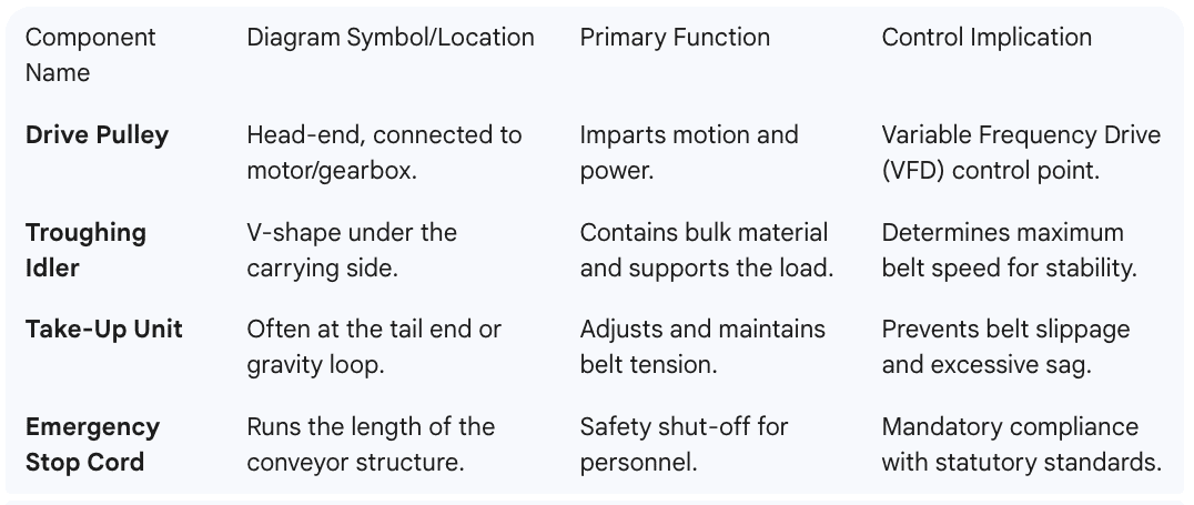
Pulleys (Drums): These circular components are the system’s actuators. The Head Pulley is the main drive. Conversely, the Tail Pulley is at the opposite end. Snub Pulleys increase the belt’s wrap angle around the drive pulley.
Idler Rollers: These support the belt and the load. Carrying Idlers are on the top (load) side. Return Idlers support the empty belt underneath. Impact idlers are specifically placed beneath the loading chute. They absorb the force of the falling material.
Belt Scraper/Cleaner: These mechanisms are located near the head pulley. Their function is to remove residual material (carryback) from the belt’s surface. This removal prevents material build-up on return rollers.
Frame/Structure: This element is usually a steel truss or channel. It holds all moving parts in strict alignment. Structural integrity is essential for safe operation.

Maintaining Alignment and Tension
Proper system performance hinges on correct belt tracking. The conveyor system belt conveyor diagram specifies idler alignment tolerances. Tracking issues often originate from improper installation or material accumulation. Furthermore, the diagram indicates the required travel length for the take-up assembly. This travel ensures the system can compensate for belt stretch over time. Therefore, adherence to these tolerances is a critical maintenance checkpoint.
Q&A Section: Expert Insights
1. What does ‘lagging’ on a pulley mean in the diagram?
Lagging is a protective and high-friction covering. It is shown on the drive pulley in the diagram. It prevents slippage and reduces wear on both the pulley and the belt.
2. Where are Impact Idlers shown and why?
Impact idlers are placed directly under the loading or transfer chute. They are shown with reinforced frames and cushioned rubber discs. This design absorbs the impact energy of falling material.
3. What is the significance of the gravity take-up loop in the diagram?
A gravity take-up loop uses weights to constantly apply tension. It is a highly reliable automatic tensioning system. It eliminates manual adjustments and prevents belt damage from over-stretching.
4. What is the ‘angle of incline’ represented in the diagram?
The angle of incline is the vertical change in the conveyor’s path. It is often labeled in degrees or as a ratio (e.g., 1:5). This angle must be less than the material’s angle of repose.
5. Why must the frame be clearly detailed in the diagram?
The frame’s detail specifies the structural material and cross-section. This ensures the frame can support the dynamic and static loads. Consequently, it guarantees compliance with structural safety codes.
Ready to implement a flawlessly engineered material flow system? Contact CDS-Lipe today to partner with a trusted engineering expert for your automated material handling systems.